Reverse Engineering for CAM Files
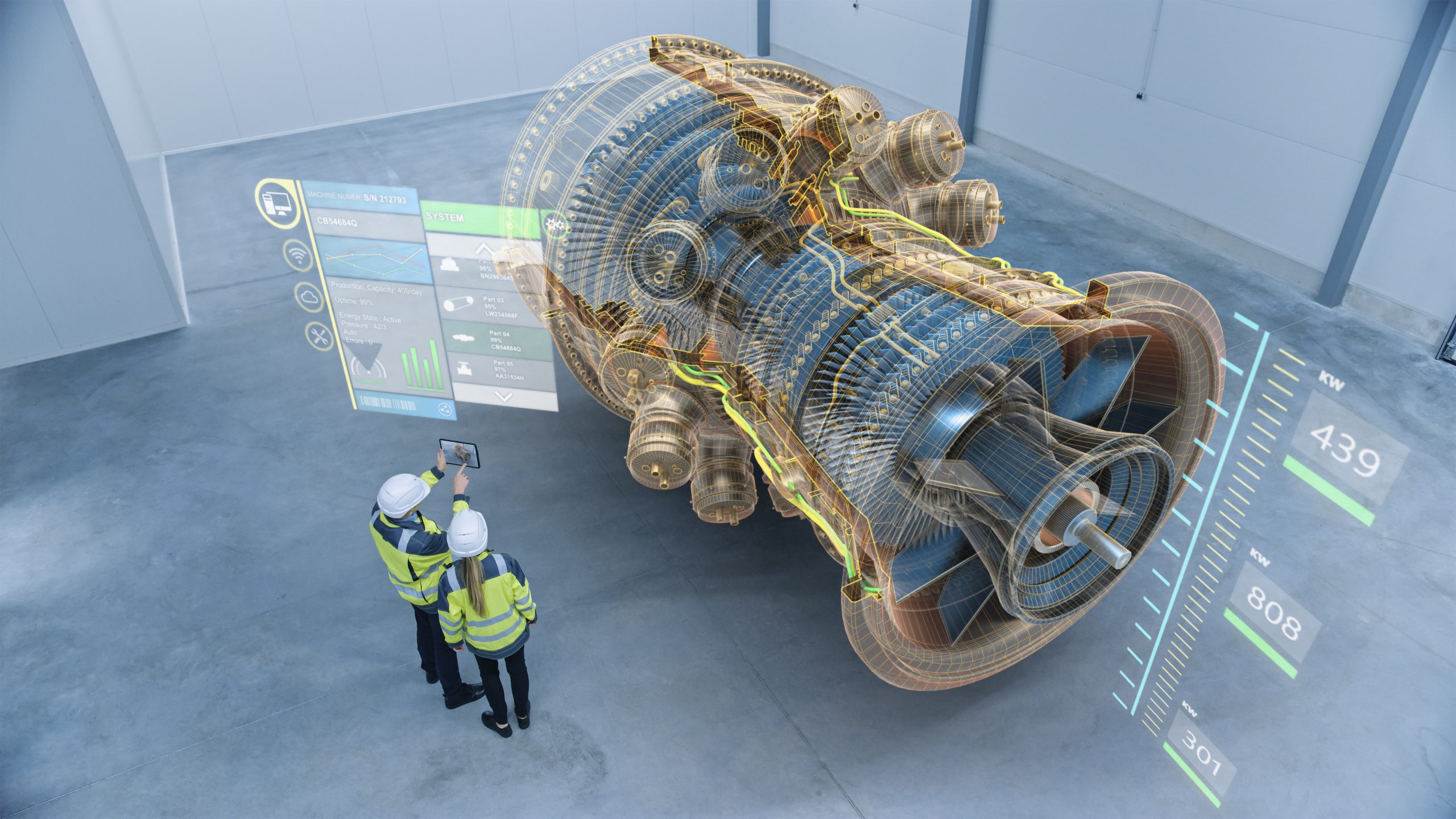
Reverse engineering for CAM files involves extracting the underlying geometry and manufacturing instructions from an existing computer-aided manufacturing (CAM) file. This process allows engineers to gain insights into the design intent, manufacturing processes, and material properties used in the creation of the original part.

Steps Involved:
- File Import: The first step is to import the CAM file into the desired software application. This may require specialized software or conversion tools if the file format is not natively supported.
- Geometry Extraction: The software then analyzes the CAM file to extract the underlying geometry, such as 3D models, surfaces, and solids. This geometry represents the desired shape and form of the part.
- Toolpath Reconstruction: Next, the toolpath data is extracted from the CAM file, providing detailed instructions on how the part should be machined. This data includes information such as the tool types, cutting parameters, and travel paths.
- Process Parameter Estimation: In addition to geometry and toolpath, the reverse engineering process can also extract process parameters, including cutting speeds, feed rates, and material types. This information can be valuable for understanding the manufacturing conditions used during the original part production.
- CAD Model Generation: The extracted geometry and process parameters can be used to create a CAD model. This model can be used for further analysis, modification, or reuse in new design projects.
Benefits of Reverse Engineering CAM Files:
- Design Verification: Reverse engineering allows engineers to verify the accuracy and completeness of original CAM files.
- Engineering Analysis: The extracted geometry and process parameters can be used for engineering analysis, such as simulating manufacturing processes or optimizing part performance.
- Repurposing: Reverse engineered CAM files can be repurposed for use in different manufacturing systems or for producing modified versions of the original part.
- Education and Training: Reverse engineering can be used for educational purposes to understand the principles of CAM and manufacturing processes.
Applications:
Reverse engineering for CAM files finds applications in various industries, including:
- Aerospace
- Automotive
- Medical devices
- Energy
- Electronics## [Reverse Engineering for Cam Files]
Executive Summary
Reverse engineering cam files involves extracting critical design parameters and geometric data from existing cam profiles. This process enables manufacturers to replicate or modify cam designs, reducing lead time and development costs. By leveraging advanced software tools and techniques, reverse engineering empowers engineers to analyze complex cam profiles, identify design flaws, and optimize performance.
Introduction
Cam files, instrumental in controlling the motion of mechanical systems, are vital components in various industries, including manufacturing, automation, and robotics. With the advent of sophisticated 3D scanning and computer-aided design (CAD) software, reverse engineering has become a valuable tool for manufacturers seeking to leverage existing cam designs or create custom solutions.
FAQs
-
What types of cam files can be reverse engineered?
- Circular cam files
- Cylindrical cam files
- Face cam files
-
What is the primary purpose of reverse engineering cam files?
- Replicating or modifying cam designs to reduce development costs and lead time
- Analyzing complex cam profiles to identify design flaws and optimize performance
- Creating custom cam designs to meet specific application requirements
-
What are the key benefits of reverse engineering cam files?
- Reduced development time and costs
- Improved design accuracy and efficiency
- Enhanced performance and reliability of cam-operated systems
Subtopics
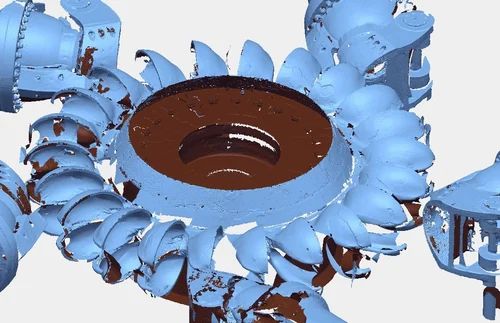
1. 3D Scanning
- Scanning Techniques: Laser scanning, structured light scanning, contact scanning
- Data Acquisition: Capture precise geometric data of the cam surface, including shape, dimensions, and contours
- Image Processing: Convert raw scan data into a digital point cloud representation for further analysis
2. Point Cloud Processing
- Data Preprocessing: Noise removal, point cloud alignment, and surface reconstruction
- Feature Extraction: Identify characteristic features of the cam profile, such as lobes, ramps, and dwells
- Geometric Modeling: Create a parametric CAD model based on the extracted features, allowing for design modification and analysis
3. Cam Profile Generation
- Cam Generation Algorithms: Employ mathematical equations and curve-fitting techniques to create cam profiles that meet desired motion requirements
- Optimization Techniques: Iteratively refine cam profiles to optimize performance characteristics, such as smoothness, acceleration, and jerk
- Motion Simulation: Validate cam profiles using dynamic simulation software to ensure accurate motion control in the intended application
4. Material Selection and Manufacturing
- Material Considerations: Determine appropriate materials based on factors such as wear resistance, strength, and corrosion resistance
- Manufacturing Processes: Select manufacturing processes suitable for the material and desired精度, such as CNC machining, grinding, or 3D printing
- Quality Control: Implement quality control measures to ensure dimensional accuracy and surface finish meet design specifications
5. Testing and Verification
- Mechanical Testing: Perform physical testing on manufactured cams to verify performance, durability, and reliability
- Software Simulation: Validate cam performance using simulation tools to assess system dynamics and identify potential issues
- Field Validation: Conduct field tests to evaluate cam performance in real-world operating conditions and make necessary adjustments
Conclusion
Reverse engineering cam files offers a powerful approach for manufacturers seeking to leverage existing designs, optimize performance, and reduce development costs. By utilizing advanced software tools and techniques, engineers can extract critical design parameters, identify potential flaws, and create custom cam solutions to meet specific application requirements. The benefits of reverse engineering extend beyond cost savings, as it empowers manufacturers to innovate, improve product quality, and accelerate time-to-market.
Keyword Tags
- Reverse Engineering
- Cam Files
- CAD
- 3D Scanning
- Cam Design Optimization